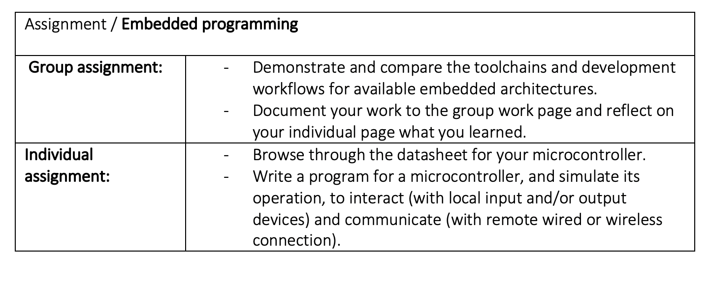
Embedded Programming
These systems can be programmed in the assembly language of the microcontroller or microprocessor or using other C or C++ languages by means of specific compilers.
From this perspective, they are generally developed for use in tasks involving real-time computing, but there are also other cases such as Arduino and Raspberry Pi, whose purpose is more oriented to the design and development of applications and prototypes with embedded systems from graphical environments.
Group Assignment
Introduction
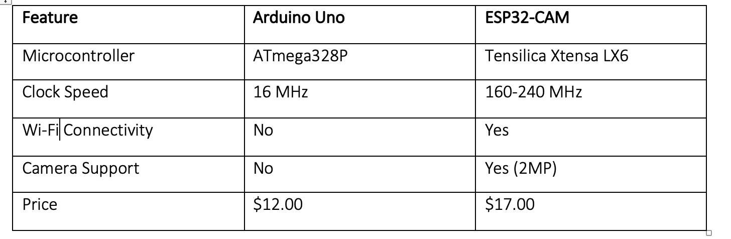
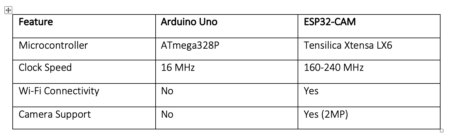
This practice compares Arduino Uno and ESP32-CAM in terms of specifications, functionalities, applications and performance.
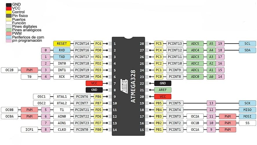
Microcontroller Pinouts
Arduino Uno
Comparative Table
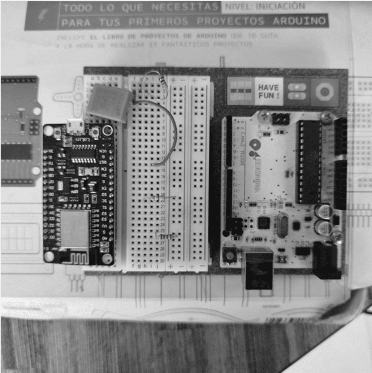
Testing Arduino Uno and ESP32-CAM for LED control and image capture via WiFi.
Step-by-Step Guide to Replicate the Group Assignment
Step 1: Gather Required Materials
- Arduino Uno board
- ESP32-CAM module
- Breadboard and jumper wires
- LEDs, resistors, and electronic components
- Power supply (5V for Arduino Uno, 3.3V for ESP32-CAM)
- MicroSD card (for ESP32-CAM image capture test)
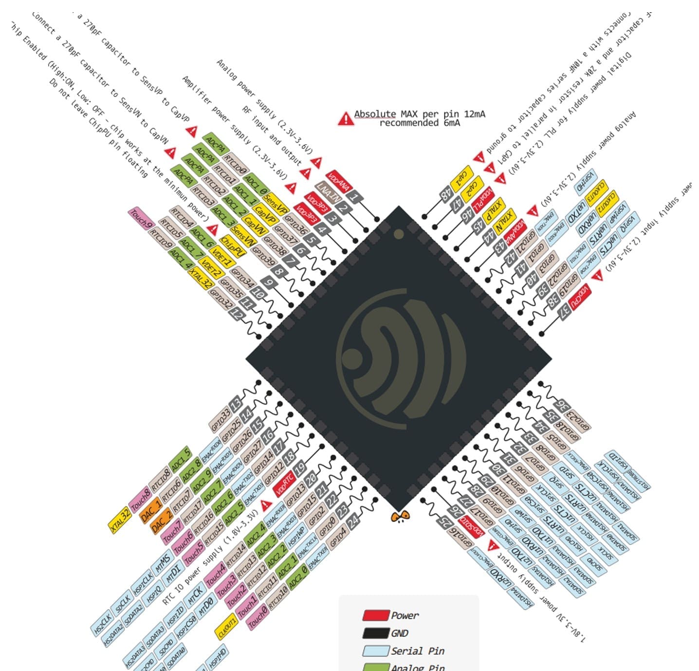
Step 2: Understand Microcontroller Pinouts
Review the Arduino Uno and ESP32-CAM pinout diagrams to identify available GPIO pins.
Step 3: Compare Specifications
Step 4: Build the Test Circuit
Connect the components according to the pinout:
- Arduino Uno: Connect an LED with a 220Ω resistor to a digital pin.
- ESP32-CAM: Connect the OV2640 camera module and a power source (3.3V).
Step 5: Implement & Upload Code
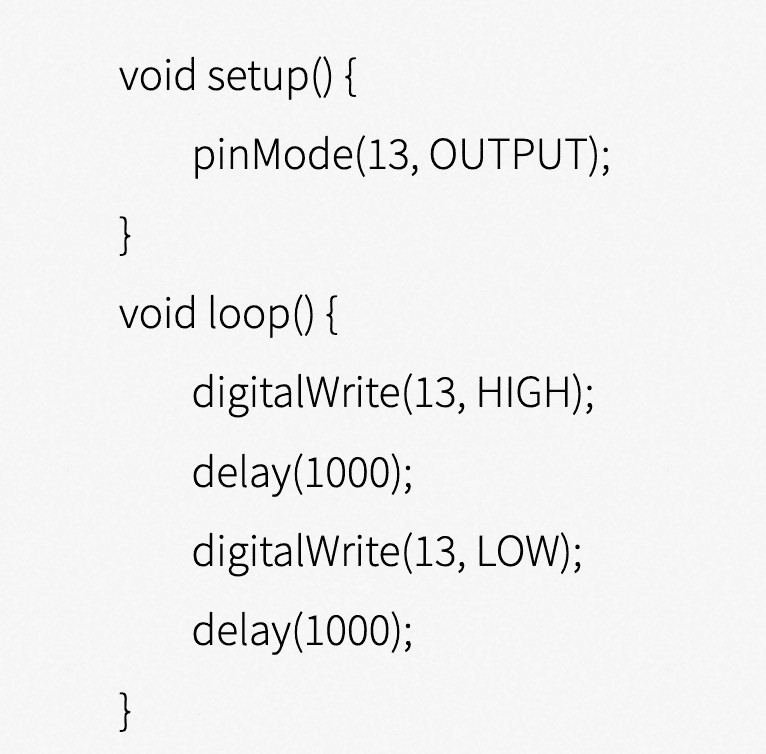
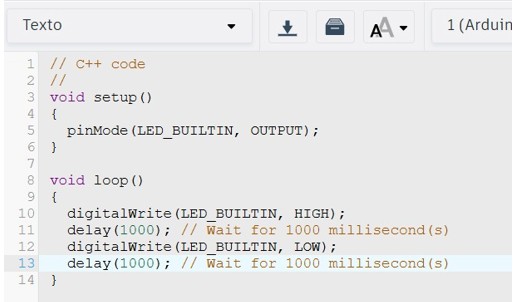
Arduino Uno LED Blinking Code:

ESP32-CAM Image Capture Code:
Upload the Camera Web Server example in the Arduino IDE and set WiFi credentials.
Step 6: Conduct Practical Experiment:
Test LED blinking on Arduino Uno and image capture via WiFi on ESP32-CAM.
Conclusion
For basic projects, Arduino Uno is ideal, while ESP32-CAM is better for IoT and image processing applications.
Step-by-step guide to setting up and working with different embedded architectures on Windows.
1. AVR (ATtiny and ATmega)
Installing Tools
- Download and install WinAVR
- https://sourceforge.net/projects/winavr/
- Run the installer and follow the instructions.
- Add C:\WinAVR\bin to the system PATH.
Compiling and Programming AVR
Write C code in a file main.c:
Compile with AVR-GCC
avr-gcc -mmcu=atmega328p -Os -o main.elf main.c
avr-objcopy -O ihex main.elf main.hex
Upload the Code with avrdude
avrdude -c usbasp -p m328p -U flash:w:main.hex:i
2. ARM Cortex-M (STM32 and SAMD)
Installing Tools
- Download and install GCC ARM Embedded from https://developer.arm.com/downloads/-/gnu-rm
- Install OpenOCD from http://gnutoolchains.com/arm-eabi/openocd/
Compile with arm-none-eabi-gcc
arm-none-eabi-gcc -mcpu=cortex-m4 -mthumb -o main.elf main.c
arm-none-eabi-objcopy -O binary main.elf main.bin
Upload the Code with OpenOCD
openocd -f board/stm32f4discovery.cfg -c "program main.bin verify reset exit"
3. ESP32 (Xtensa and RISC-V)
Installing Tools
Download and install ESP-IDF from https://github.com/espressif/esp-idf
Compile with idf.py
idf.py build
Flash the Code
idf.py flash
4. Raspberry Pi RP2040
Installing Tools
- Download and install Pico SDK from https://github.com/raspberrypi/pico-sdk
- Install CMake from https://cmake.org/download/
- Install Ninja from https://github.com/ninja-build/ninja/releases
Compile with CMake and Ninja
mkdir build && cd build
cmake ..
ninja
Upload the Code
Connect the RP2040 in bootloader mode and copy the .uf2 file to the device.
Conclusion
This guide provides a structured approach to setting up and working with various embedded architectures, covering AVR, ARM Cortex-M, ESP32, and Raspberry Pi RP2040. Each toolchain has its specific workflow, but all share common steps: installing the required tools, writing and compiling code, and flashing the compiled binary onto the target hardware. Understanding these processes helps developers choose the right platform for their embedded system projects.
Individual Assignment
Introduction
A signaling device that controls vehicular and pedestrian traffic at intersections. Traffic lights operate through a system of red, yellow and green lights. It is programmed to change colors based on a defined time schedule.
Materials
- ESP32 development board
- 3 LED lights
- Resistor
- Breadboard and jumper wires
- https://wokwi.com/projects/424561247322728449
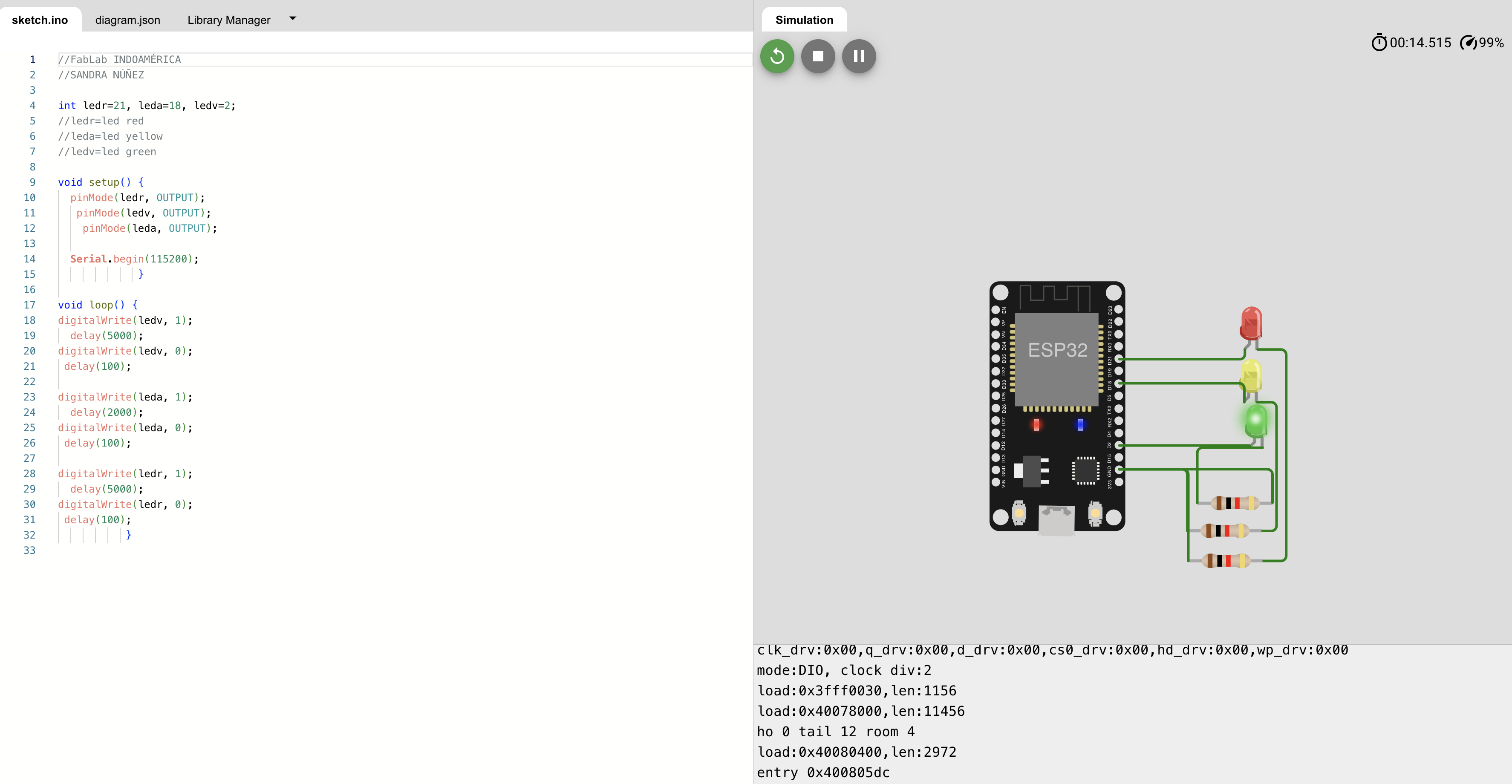
Circuit Diagram
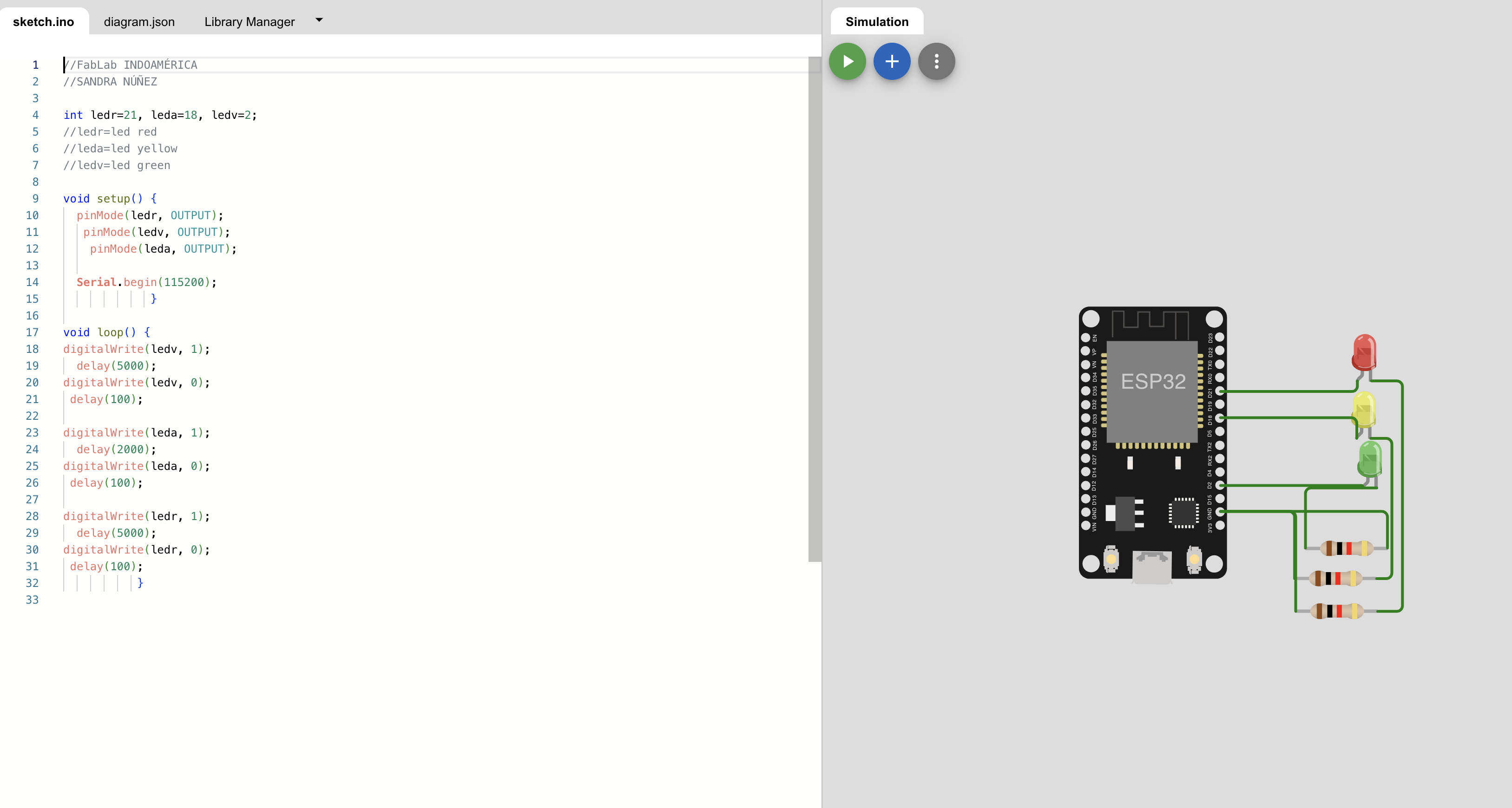
Code Implementation
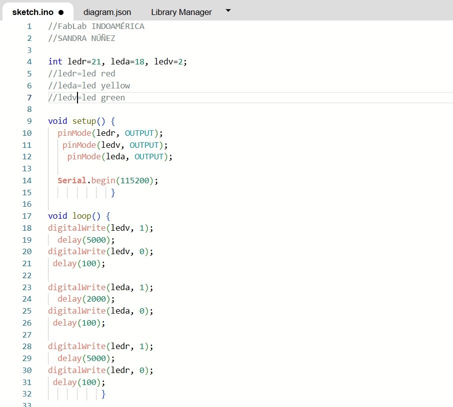
Simulation & Testing
The circuit was tested on Wokwi. It is programmed to change colors based on the defined time schedule.
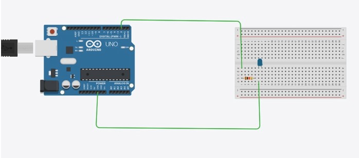
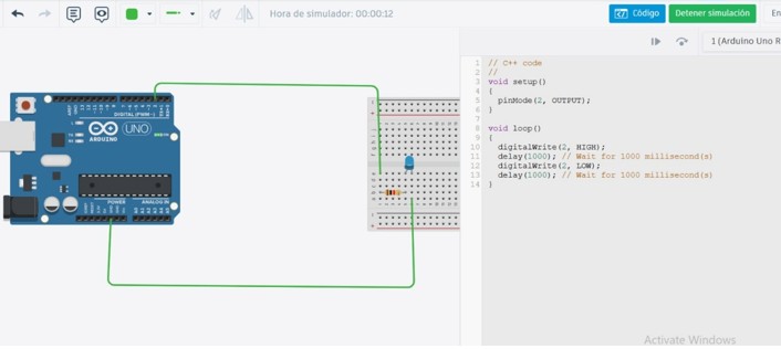
Additional Simulation: Tinkercad
Another simulation example was carried out using the online platform Tinkercad. In this case, a basic traffic light circuit was simulated using an Arduino UNO.
Final Conclusion
This project allowed us to experiment with a signaling device. The traffic lights work with a system of red, yellow and green lights and are programmed to change color according to the defined schedule.